Tuesday, December 10, 2013

The New Name

A while back, I realized that the name Wolf River & Nicolet was out of place: The Nicolet Forest wasn't so named until sometime in the 1930s, when the federal government took it under protection as part of the effort to re-propagate it. So began a lot of ruminating and dithering as I contemplated a new railroad name. In the process I also thought more clearly about the railroad concept.

The end of all that has resulted in the name Wolf River & Lake Superior Ry. Co., a short line that grew out of a logging line but attained common carrier status and links Green Bay and Superior in an arc across northern Wisconsin through the woods and lakes around Eagle River and then the Lake Superior Shoreline through Ashland. At more than 300 miles from terminal to terminal, it's a bit long for a true short line, perhaps, and being the 1930s, it's struggling to remain independent. Expect trains from the C&NW and perhaps the Milwaukee Road to make use of its tracks from time to time.

And we have a settled-on herald as well. Here it is:


Thursday, December 5, 2013

Further Revisions

Mostly these days I am mumbling in the corner and thinking out loud about this railroad project over at the Model Railroad Forums (see the blogroll).

But I will bring things a little up to date. After some further tweaking of the track plan, I have it about as complete as I think I can.


(The color coding has been just to make it easier for me to do some grade calculations when working on the plan in SCARM, the free Model Railroad CAD program I've been using. It has no other significance. I've been assured that based on the scale of my plans for operation, I probably do not need to divide this into power districts. That said, I may actually gap it for power districts now with the idea that I would implement them later.)

The biggest further change has been to add a combined reverse loop (mostly hidden) and wye (mostly visible) in one corner to make it possible to run out and back operations, either from staging to staging and back, or from Eagle Junction to either staging  and back. Through trains can start in staging and run from St. Matthew through Eagle Junction and Aaronsburgh and back to staging, or they can run the opposite direction.

I will probably make further revisions, particularly to Aaronsburgh, now that I am in the 1:1 planning stage. My objectives with Aaronsburgh will be to both allow for as much operation as possible (in other words, increase opportunities for picking up and dropping off cars) but also to make sure there's room for the urban scene (albeit small, northern Wisconsin, 1930s urban :-) ) that I envision.

The triangle to accommodate the wye/loop at St. Matthew hasn't been built, and won't be until the actual planning is complete. I want to make the loop and wye occupy as small a space as possible so as to make the triangle as small as possible, and I'm reserving that task for the 1:1 planning phase that I am now entering.

I've put the first 2-inch layer of foam on 3 of the 4 sections. The fourth piece just needs to be cut to fit, and I need another tube of adhesive for it.

Sunday, August 25, 2013

Name Change?

I'm thinking about changing the name of my fictional prototype railroad from Wolf River & Nicolet. It turns out that the Nicolet Forest didn't get that name until the 1930s. Although I am setting the railroad in that decade, it doesn't seem plausible to me that the name would have predated the forest's having been named that. (The US Forest Service named the forest for the 17th century French explorer Jean Nicolet.)

I really like the ring of the name, but even though it is freelanced, I do want it to be as plausible as it can be given the setting in geography and time. And I also have second thoughts about the use of Wolf River. As far as I can tell,  names of carriers in the region reflected communities served, rather than just geographic features.

So I think a name change is likely...

Thursday, August 22, 2013

Revised Track Plan

A few weeks ago I ran into a professional in the model railroading field. We met a few years ago when I wrote about Milwaukee's unique status as a center for the hobby. When I had interviewed him, I mentioned I was itching to finally get going on a layout. On the occasion of our reconnection, he asked whether anything had come of that, and I told him that, indeed, it had.

"Well if you ever need any advice on anything, just send me a note," he said -- and not just once, but several times -- so I think he wasn't just being cordial.

So I sent him the plan I posted previously, and got back a detailed and helpful assessment of it. He thought it was pretty good, but suggested some changes: Improving the reach at Aaronsburg, reconfiguring the siding and yard at Eagle Junction so that the yard and engine terminal was closer at hand to the central operating area; making the staging track double ended; and bringing the three tracks on the lift-out close enough together that the lift-out itself can be narrower than 18 inches originally contemplated.

Taking his advice to heart, I revised the plan. Probably the biggest change was getting rid of the triangular space in the upper right corner of the operating area so that the reach to Aaronsburg is now within 2 feet or so. The staging area also underwent some major revision, and various other tweaks were made.

I like the way it looks.


The full plan


Staging details


Visible Track Only


I've only added two structures: The engine house (A Walthers kit I bought some time back on eBay), and a planned brewery that will be part flat, part 3-d structure, located in Aaronsburg.

And for the fun of it, here are some 3-D renderings of the layout.


Friday, August 9, 2013

We have a trackplan

I've been working on the details this week. I decided to use a freeware program for this purpose... pretty cool, actually.

Here is a trackplan, in a couple of forms, and then a rendering 3-D style...


Friday, July 26, 2013

Thank you, Craigslist!

Last night DairyStateMom, DairyStateKid-M, and I hauled home four slabs of 4x8 by 2 inch DOW Styrofoam XPS insulation board. I bought the material at a substantial discount from a guy who had it leftover from a siding job on his home. (The seller kindly helped make it easier to haul in our small vehicles by slicing it into smaller pieces under my direction, reflecting how it would be cut up for the layout.)

I'd been looking for a few weeks for a cheaper source of this stuff, the favored scenery and roadbed material for layouts. Now I have enough for the entire layout. I may need to get a bit more either half-inch, three-quarter-inch, or one-inch thick, but even of that I have some other leftover stuff courtesy of a friend.

The final benchwork section is about two-thirds finished. When it's all together -- this weekend, perhaps? -- I'll post pictures.

Now it's time for me to return to the track plan details. Of course it would have made sense to firmly work out the track plan before even building benchwork, but as I have reported previously, the benchwork was originally constructed with a completely different configuration in mind and only repurposed when I concluded I could do a lot better than the first configuration.

As for the track plan itself, I have compiled a ton of different plans from which I can draw particular concepts for the new configuration. I have a clear idea conceptually for the plan now, but precise elements remain to be developed.

If I don't have the plan finished by about mid-August, I plan to take my drawing supplies on a vacation and hope that by my return, those details will be sufficiently finalized to enable me to start putting down cork roadbed and track -- maybe even by Labor Day weekend!


Tuesday, July 16, 2013

Typefaces: Updated

A couple of months ago, I posted a selection of typefaces, using the HTML editor to render them. I've realized that they were not consistent from one computer and browser to another. So while I am leaving that post up, I decided to make a new post presenting the same document as a graphic. I hope this will show more consistently the various typefaces I am considering in connection with the Wolf River & Nicolet Ry. Co.

As before, if you wish to comment on which you like best, you would be welcome to do so.

A note, too, on time period, as that might be relevant to evaluating appropriate typefaces: My greatest preference would be to set it in the 1930s, just after Prohibition. I am trying to ascertain, however, whether that is an appropriate time period for the scale of logging I would like to depict. I don't mind if this is an era in which logging is in decline in Northern Wisconsin, which by all I have read so far it certainly was, but I want it to be at least realistic and appropriate to have some continuing logging and railroad operations associated with it in this period and locale.

If in time I conclude that is too far removed from reality (even for a freelanced railroad), I will fall back to the first 20 years or so of the 20th Century, before Prohibition.

If you have any knowledge and information you'd like to share on these points, you're more than welcome to do so in the comments.


Saturday, July 13, 2013

Never finished...

It's supposed to be the model railroad that's never finished.

But the benchwork?

A couple of weeks ago, I assembled a supplemental section to complete the circuit and allow for continuous running. The added section was built fairly quickly, and used a much more basic approach: essentially, a flat 5/8-inch thick plywood piece with legs. It was further divided into two sections, so that one could be a lift-out.

 When I was finished, though, I wasn't satisfied. Then I finally let myself see another possibility that I had been resisting for the four original sections:  To move the other section A from the right side of the configuration to the bottom, and put a new section along the right side. Because that is the side open to the rest of the room (see the configuration situated in the overall room in this post), that's really what made the most sense for access. See the image just above at right.

Note, too, a couple of very small additions where the main sections have to be offset so that the configuration works properly and that there is overall enough clearance in the room. Those will be very basic, just bolted to the existing sections and needing no major support.

Of course, that changed the dimensions for the new section, which gave me a justification for starting over on it. So the original added section has been put aside (I will probably cannibalize some of the lumber). In its place, I am building a full-fledged section, to be supplemented by a small lift-out to allow easy access to the center:


The principal new section will be 18 inches wide. It will be framed differently than the other four. Those used a modified form of Jim Hediger's popular and very successful ripped-plywood framework, with bolted legs. The new section will be ripped plywood framing, the pieces will be smaller and lighter, and the support will be a simple L-girder system. I've been reading, and re-reading, about this in 102 Realistic Track Plans from several years back, and wishing I had followed my initial instincts to use that system from the start.

So once again, the next step -- putting down a layer of insulation foam -- is being put off...


Friday, June 28, 2013

What!??!!?!?!


I will be the first to admit, I am no expert carpenter. But still...

As previously reported, I have rearranged the layout sections I built previously into a new configuration for which I am designing a new track plan. In order to arrange continuous running, I am building another section (using somewhat different methods -- more on that later) that will turn the upside-down-U-shaped arrangement of existing sections into an O. (The unlabeled section across the bottom represents the new section.)

Going clockwise starting with the A section at the left in the above image, I have gone around leveling each section and making sure it connects smoothly with its mate. Then, as each section is leveled, it is bolted to the previous section. In this manner I have leveled and attached left-hand A to left-hand B, then left-B to right-hand B. All is well...

So what remains is right-hand A to be leveled and bolted to right-hand B, then the new section to be completed and everything bolted together. (A portion of the new section will be a lift-out to avoid having to duck under.)

In theory, the two A sections should be parallel, with an identical distance between them at either end.
In reality . . .

. . . they are 1/2-inch farther apart at the bottom (in the above image) than at the top!

How did that happen?

I did my best to keep everything square as I was assembling things. But obviously, I didn't quite succeed.

I will have to make up the difference by tweaking the final section, and specifically, I think, the lift-out portion. I will probably do that by adding some filler (in the form of a piece of scrap lumber) to the appropriate place on the lift out (or, maybe, on the part of the final section that is fixed and does not lift out).

Still, it drives me nuts that this has happened, and it's slightly depressing.
I do have, though, one consolation . . . or maybe, this one . . . 


Sunday, June 23, 2013

Step by step

So, I'm working on some details.

The layout will include one new section, already sketched in to the benchwork plans: To allow continuous running, I am adding a 1-foot wide shelf unit at the bottom of the benchwork arrangement. For several weeks now I have been working on engineering that section.  I  have finally worked out most of the structural details, including making part of it use an elaborate lift out segment. Although this part is just the equivalent of a shelf, the benchwork is complicated for that reason. But the project is coming along, and I hope to share details sometime....

Friday, May 24, 2013

Does It Ever Stop?

The evolution thing, that is? :-)

Just came across yet another variation on the basic new design that I've come up with: This plan from MR a while back. It's got some great ideas that are helping me further refine my concept, particularly regarding staging.


Although this plan is all on one level, nothing says it has to be.

It all just gets better and better...

Tuesday, May 21, 2013

Trying Out Typefaces: Updated

I am leaving this post in place, but removed the graphic element, which didn't translate consistently. See the NEW "typefaces" post here.

Playing with a series of different typefaces in Word to settle on a typographic style to use on printed material, heraldry, etc. I've always been partial to "Ry. Co." instead of "R.R." so these reflect that usage, but I might change my mind and revert to the more common terminology...


(The way the top line is jammed to the second line, if it is, is an artifact of Blogger... That is not the intent of the design. I am not sure how to fix that here and I don't want to take the time to figure it out.)

If you happen by these parts and have an opinion about which of these you like best, feel free to chime in in the comments. (You can identify your preferred face by the name in smaller type immediately below it.)

The premise is a fictional line in northern Wisconsin in the 1930s, primarily handling local traffic, but with some through traffic passing over it from Green Bay to northern Minnesota (Duluth/Superior). The primary local traffic includes logging (there will be a branch serving a logging camp, and there also will be a small sawmill to deliver the logs to), a brewery, and iron ore (haven't decided yet if there will be a mine on the existing layout or "off stage". Local way freight of various kinds and limited passenger traffic will round out the picture. A number of details are up in the air, but the location, setting, and logging theme in particular are fairly definite. A friend who is an angler recalls passenger trains that took people up north in years gone by during the fishing season, so that might be part of the mix, too.

Power will be smaller steam; the largest might be a 2-8-2 for freight or 4-6-2 for passenger service, but mainly it will be 2-6-0s, 2-6-2s, and probably a Consolidation (2-8-0). And at least one or more geared locos mainly serving the logging and perhaps mining traffic.


Re-Routing, or, Evolution Redux

So here I thought I had everything figured out, once again.

Working with the layout footprint I had most recently settled on, I set about refining my track plan. For the most part it came together pretty clearly. But there was one hitch.

The ideal benchwork outline would have been the one I first arrived at when I decided to abandon the original configuration of the four sections I made:
But since that didn't fit the allotted space, I had to tweak it. I thought the new configuration was going to work: 
But as I began working out in earnest details of the offset section (upper left corner in the above diagram), it became clear that things were not going to pull together.

One reason for this was that I was getting stubborn about wanting to use curves larger than 18-inch radius for the main line. Having initially resolved to do that, I found it nigh impossible to back away from that decision. And as a result, the track that bends around the inside aisle way took up lots of space, and things just didn't work properly.

So it was back to step 1, or, since I am working with the sections I have already built, I guess you could say, Step 1.5.

I spent most of yesterday evening first trying to make the above concept work, then doodling when I couldn't get it to my satisfaction. I went to bed, still pondering.

At about 1:30 in the morning I woke up. Suddenly, an inspiration seized me.

I sketched out an alternative arrangement of the sections. It looked like this:

Then, I thought, I could build a final additional section to create a connecting stretch of track that would permit continuous running. 

There was another possibility along these lines: Putting the two "B" sections against each other 4-foot-side to 4-foot side. That would have created a 4-by-6 foot base that could accommodate a full oval loop, with track then branching off of it onto the "A" sections. But  then the arrangement would be 10 feet wide, with the big base 4-feet deep, requiring access from all sides. The only way that would fit in the layout space, there would have been no possible access to the back side of the 4-foot-wide segment.

But if I butt them together 3-foot side to 3-foot side, as above, that creates a 3-by-8 foot base. I don't need to accommodate a full loop now (although it might be possible with some added benchwork on the inside corners between the A and B sections, which I'll get to in the fullness of time), because suddenly, I can do a full "around the walls" style. The new 1-foot-wide section can be built in such a way as to make for a not-too--difficult duckunder. 

And finally, this one fits nicely in the same footprint in the room as the previous "final" approach. 


Note that the "B" sections have easy access from all sides, that the closet to the right remains accessible, and that the bookshelves are accessible as well ("Thank you!" says DairyStateMom.) 

I've already started sketching out a new approach to the plan using this arrangement. I'm seeing on the combined "B" sections staging on the lower level and a pretty substantial station/yard/engine terminal scene above the staging (mind you, for a small railroad, not a Class 1). The track plan will basically be a twice-around, with track going from the staging area at either end, then looping around the "A" sections and the new 8-by-1-foot section to ascend to either end of the "B" section centerpiece. This next design is going to be a starting point: it, too, has a 3-by-8-foot focal area (the right-hand portion of the plan) with staging beneath it (that's where I got the idea). But the remainder will be quite different, although the broad twice-around schematic remains:


Additional details and ideas are likely to come from these next two, although my space is smaller than either of them:

So now it's back to drawing the plan all over, nearly from scratch. 

OK, am I really finished this part now?


Tuesday, May 7, 2013

The Route Ahead

(Image linked from Wikimedia Commons. Click here for image credit and other details.)

So here's what is next on the agenda:

1) Firm up the track plan, drawing at a scale of 1.5 inches to the foot.

I'll post something about my improvised approach to turnout templates for track planning, too. And along the way I will share the fictional tale of this North Woods Wisconsin enterprise.

2) Once the track plan is firmed up, build the three "floater" benchwork segments. I want to do that after the track planning because their exact dimensions are subject to change based on the needs of the plan itself.

3) Settle on two specific track selection questions. I have already chosen Micro Engineering Code 70 flex track for most of my track, with Micro Engineering Code 70 #6 turnouts as my turnouts of choice. But I expect I will want at least some curved turnouts, so for them I will need to decide between Shinohara Code 70 #6-1/2 curved turnouts or, perhaps, Peco Code 75 curved turnouts (not sure what size). I will be asking the proprietor of the train store I favor about which is the better choice. (For planning purposes, I'm using Shinohara 6-1/2 templates, on the theory that that is "close enough for rock-n-roll" and that I will be doing a 1:1 scale sketch of the track on the base before laying any down, so that I can make adjustments accordingly.)

The other track selection question is whether I will want to deploy any turnouts that are sharper than #6, which appears to be the only size ME makes. My inclination is to stick with #6, but to give myself "permission" to opt for the tighter turnouts if absolutely necessary. If I do, I'm leaning toward Shinohara Code 70 #5 or #4-1/2. I don't know if I will need to use any wye turnouts, but if so, Shinohara Code 70 again probably gets the nod. In each of these instances, though, I will give the Peco Code 75 a look as well.

4) Purchase and install extruded styrene insulation board for subroadbed. For the tabletop level, I will use 2-inch sheets. For grades, I will probably use the Woodland Scenics risers combined with the insulation board material. And for the upper level subroadbed, I expect to use 1/4-inch luan (which is what the base level table tops are) topped with, probably, the 1-inch insulation board (but possibly the 2-inch), and supported by layers of the insulation board in appropriate thicknesses. Once the tabletop level insulation board is in place, I will then draw out the bottom level trackage. As you'll see when I post the final track plan, the design allows for continuous running early on with a full circuit of track before I have to build any of the elevated track.

5) Decide, once and for all, how to power the thing. I only know DC, I have little in the way of equipment, I am intimidated by the cost of DCC add-ons, but I know deep down that DCC is almost certainly the way to go for the long term.

So, follow along as the story unfolds. Comments (so long as they're respectful and constructive) are welcome. So is advice, which I will consider and then either take, or not take, as I choose -- so if I choose not to follow it, don't take it personally!


Sunday, May 5, 2013

Evolution of a Track Plan


So three years ago, this was the track plan I had settled on: (This is a very rough tracing of the original, published in the August 2005 issue of Model Railroader.) :


I chose it because first, I wanted a sectional layout. My reason was mainly that, having waited this long in my life to get going on one, I didn't want to have to tear it down in 5 or even 10 years if we wanted to move. The original designer of the layout above conceived it as a portable layout. (Check out the original article for details.) I liked it because it had continuous running, it had several distinct points on it (3 or 4 communities/station stops), and even a branch that could lead to a logging camp (or a mine, but ultimately I settled on a logging camp). As originally conceived by the designer, it was of a Texas shortline with desert scenery, but I saw it would be easy to modify scenically to depict Wisconsin's North Woods, the setting for my railroad.

As originally designed, the layout is portable, with two long sections that fold back to back and two 'wings' that fold down from a 90-degree angle to flat. I took the basic concept, but instead of following the identical dimensions and construction techniques for total portability, basically treated the various segments as individual sections in a sectional layout. The result was four sections of portable benchwork: two segments that were each 6 feet-9 inches long by 2 feet wide (labeled "A"), and two that were 4 feet by 3 feet ("B"):


The basic track plan would stay the same -- in fact, with the configuration, it almost had to stay the same. I spent some time working on details, testing a few variations, and so on, but couldn't really stray from the plan as drawn.

Yet there were some real challenges in the design. I didn't really care for the s-curve in the tunnel between the sites I called Aaronsburg and St. Matthew, for instance:


I had great reservations about the track up at the upper right corner that, after getting up to 3 or 3.5 inches above the lower level, immediately had to descend to the staging area:


And I was leery as well about the track descending from the other end of Eagle Junction, again to the staging section; I wondered if it wold really work:


So those were the kind of things that had contributed to my feeling so stuck, and, perhaps, help explain why I've been all but paralyzed over the last couple of years.

Still, a few attempts to start from scratch with the same basic group of sections led nowhere. So two weeks ago, determined to finally advance the ball, I began sketching out the detailed plan at a scale of 1.5 inches to the foot. Then I had a brainstorm: A completely different way of arranging the sections. What if...

...I put the two "A" sections at right angles to each other, and the two "B" sections at the ends of the "A" sections... Like this:


I could then add "filler" sections, the triangular segments partially outlined in red in the sketch above. They would be bolted to their adjacent sections and would not need extra legs, simply "floating" in place.

The resulting track plan just about drew itself! It went through a few tweaks but the basic approach soon fell into place:
The pencil sketch isn't great, but basically it's a loop-to-loop with a turnback in the middle. As shown here, it starts with a lower-level reverse loop in the upper right corner, then travels to the left and down, with a turnback at the lower left-hand corner. The mainline continues, rising, to the other end reverse loop, back in the upper right corner and over the lower reverse loop. At the upper reverse loop, there's an engine terminal and a branch to the logging camp. 

I expect if you look at the original track plan you can see how it was morphed from that one,. 

Exciting and liberating, but not quite perfect. Even though the leg on the right was shorter, it still extended too far into space right in front of the stairway from upstairs, when placed against the basic map of the basement room where the layout is to be built:


I tweaked the basic configuration some more. I turned one of the "B" sections 90 degrees, then offset it some, making the most of the space I had available:


I'm sparing you some slight detours that I took in working this all out. To make a long story a little shorter, here's how it fits now:

(One big bonus: A set of closets at the left of the room by this view that would have been rendered totally useless because they wereall but inaccessible when the tables were set up for the very first configuration are now completely accessible once again. DairyStateMom is very happy with that turn of events.) 


The trickiest part was fitting a full turnaround into the section that was offset. Since at this orientation it was just three feet wide, it wouldn't even quite take my minimum 18-inch radius:


But extra floater sections on the offset section, both at the outside and the inside...


... leaves enough clearance to fit a full turnaround loop in that space:


(This is, of course, very crude, made with MS Paint; but you get the idea. And as I develop the detailed plan, if the dimensions or position of either floater section needs to be further tweaked, I will do so.)

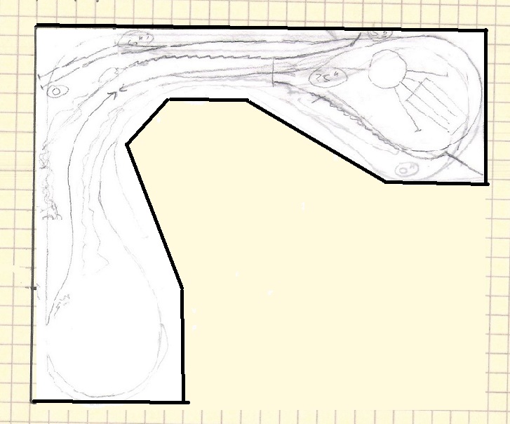
So here's the very, very rough sketch of the track plan in this final configuration:
A couple of points of note: The upper and lower reverse loops are now to the lower right in the above sketch. The logging branch still comes off the upper reverse loop, going to the lower left corner, then curving around and going up the left side part way. (So this logging branch line gets a little bit more length to it than previous iterations.)

The engine terminal, however, has now moved to the turnback loop instead of being attached to the upper reverse loop. That's because the compromise I had to make to accommodate the turnback loop left me with a fair amount of open real estate on the rest of the 3-by-4-foot section at the top of the plan.

The upper loop area, now sans engine terminal, is still to be called Eagle Junction (more on the names another time), because it is where the mining branch peels off from the main line. So the engine terminal, instead of being at Eagle Junction, now is at Aaronsburg. But that suits, too. Because this layout configuration enables a much more thought-out staging track arrangement. From the lower level loop (lower right), which is St. Matthew, there's a staging track area that runs all the way around to the left and up (essentially, right under the log mining branch) to rejoin at Aaronsburg. So Aaronsburg is also a junction.

I'll write more about all this another time. For now, it's back to the drawing board as I develop the plan in earnest.


Saturday, May 4, 2013

I'm Back

So it's been more than a year since I've posted anything here. And much longer since I've been able to take time to work on the railroad.

After the fall of 2010, things got stuck. Mostly because the volume of my work (I'm self-employed) grew to an extraordinary degree, but also because of a wide range of personal distractions involving day-to-day life.

I think, too, however, that I was sort of stuck because of a nagging dissatisfaction with the track plan that I was once so committed to.

And then the basement, and the workbench, started getting more and more cluttered... and time passed... and more time... and more time...

Until, finally, I could stand it no longer. I had to get back on track. So earlier this spring I spent a couple of days decluttering the work bench, cleaning up the basement, turning my train tables back into places where I could lay some track instead of auxiliary horizontal storage surfaces.

I got out my 17 x 24 inch pad of graph paper and bought a piece of foamcore board to use as an inexpensive drawing board. I carefully outlined the sectional set up as configured for the trackplan I had settled on way back three years (three years!) ago.

And almost immediately, as I was planning out some track, I found myself once again feeling a nagging frustration. Look, it was a nifty plan, really, but there are some grades and runs on it that just don't seem like they would work. The space on it was really tight. (Of course, that's why I picked it.)

This has happened before over the last few years, as I had buyer's remorse of sorts over the plan I'd picked, and for which I had already built four sections of benchwork. I tried more than once to rearrange them to see if I could make something else work, with no luck.

But then I had a brainstorm just a few weeks ago. I don't know why I hadn't figured this out before. But I hadn't.

I came up with a completely different way to set up the sections.

I later tweaked it a little bit more, to better deal with the space I am in in the basement. and after a few more tweaks, bingo!

And the new track plan I've devised, while taking some inspiration from the original I was considering, has so many more advantages. It's able to create a longer run, and at the same time it is going to be able to make much more gradual grades. And the whole thing just fits better in that basement, in every respect. Not only that, but while I am keeping the retractable casters I devised for two of the four sections, I don't anticipate needing to use them much at all. For most purposes, the layout can be fixed in place almost all the time. Access to a storage closet, which I thought we would lose, has been restored completely. And DairyStateMom has plenty of room to reach the two big bookcases (which we did move across the basement from where they were when the framework pictures were taken back in the fall of 2010).

I will post some drawings tomorrow or the next day showing the original sectional arrangement and the way it has evolved. In the meantime, I am raring to go once again. And this time, I have no reservations.